Fluid Power Engineering
Professional Engineering From Pneumatics to Lubrication

Fluid Power Engineering

Professional Engineering From Pneumatics to Lubrication

It’s important to take an interdisciplinary approach in this field and to include electrotechnical designs in the documentation. EPLAN has the right solution for you for these various engineering fields – combined in an integrated software environment.

Background

An Overview of the Four Subdisciplines of Fluid Power Engineering

There are four different areas in fluid power engineering: pneumatics, hydraulics, cooling and lubrication.

Pneumatics

Pneumatics is the use of compressed air to perform work in the sense of preparing energy to act on a body. Compressed air systems are usually made up of four subsystems: compressed air generation, compressed air preparation, compressed air distribution, and then, finally, the actual application.

Hydraulics

In hydraulics, oil is used to transmit power, energy or momentum in working machines.

Cooling

Cooling can be understood as the process of removing thermal energy. If heat is extracted from solids or liquids, it occurs according to the physical principle of heat transfer.

Lubrication

Lubrication can prevent friction and wear, for instance, between two parts within a machine. A suitable lubricant or lubrication method needs to be used for this.

Basics

An Overview of the Fluid Power Engineering Tasks and Challenges

You are faced with numerous tasks and challenges in your daily fluid power engineering work. EPLAN supports you in mastering these challenges and in getting the best out of your workflows.

Fluid power engineering tasks

Fluid Power Engineering Tasks

Designing the various systems for a machine or plant system is one of the most important tasks in fluid power engineering, for instance designing the compressed air supply for pneumatic systems and the oil supply for hydraulic systems, not to mention the actuators for both variants. You also need to design the plant’s control systems and document both the fluid power and electrical systems. Creating the schematics maps the connections between the various components of the four fluid power engineering areas.

Challenges fluid power engineering

Fluid Power Engineering Challenges

There are also a variety of challenges in fluid power engineering. For instance, hundreds to thousands of components need to be conceived, designed and numbered. These in turn need to be connected to one another via tubes or piping, while the diameter and lengths of these components need to be determined and each provided with an identification number. Schematics then need to be documented across hundreds of pages. Furthermore, the completed plant system need to meet the planned specifications and be transportable. In addition, a number of employees are often working on a project at the same time and the data from the fluid power engineering needs to be available for use in other departments.

Codes and Standards

Integrate Your Engineering for Code-Compliant Fluid-Technical Designs

There are various codes and standards that need to be complied with in fluid power engineering. A positive side effect is that you then also create the foundation for a uniform and standardised database for your documentation. A few important standards for creating fluid power schematics include ISO 1219, IEC 81346 and IEC 61355. Device identification is regulated by IEC 81346, which supports you in product structuring and in interdisciplinary engineering. IEC 61355 regulates the type of documentation, which is a helpful guideline for organising multiple pages of documentation in an integrated way. Code-compliant designs quickly pay off through the increased efficiency of your engineering. EPLAN solutions support you in this.

Code fluid technology engineering
Codes and Standards

Integrate Your Engineering for Code-Compliant Fluid-Technical Designs

There are various codes and standards that need to be complied with in fluid power engineering. A positive side effect is that you then also create the foundation for a uniform and standardised database for your documentation. A few important standards for creating fluid power schematics include ISO 1219, IEC 81346 and IEC 61355. Device identification is regulated by IEC 81346, which supports you in product structuring and in interdisciplinary engineering. IEC 61355 regulates the type of documentation, which is a helpful guideline for organising multiple pages of documentation in an integrated way. Code-compliant designs quickly pay off through the increased efficiency of your engineering. EPLAN solutions support you in this.

Best Practices and Solutions

All Solutions for Your Fluid Power Engineering From a Single Source

Professional fluid power designs have many criteria to fulfil: symbols, circuits, tubes and piping all need to be easy to find and use. The numbering for a variety of components should occur automatically while at the same time the parts must match the resulting bill of materials. This simplifies later manufacturing and commissioning. Creating schematics should also be able to be automated, while navigating through the designs should be easy via cross-references. Take advantage of the integrated EPLAN solutions to efficiently create your fluid-technical designs.

EPLAN Fluid

Create Fluid-Technical Schematics

EPLAN Fluid is your engineering tool especially for engineering and automatically documenting circuits in fluid-technical systems for pneumatics, hydraulics, cooling and lubrication. It allows you to master all of your engineering challenges, design code-compliant fluid power schematics, and make your data available for downstream departments with interdisciplinary involvement in the project.

EPLAN Data Portal

Device Data for Fluid Power Engineering

High-quality device data are vital for efficiently planning your fluid power designs. Questions to be answered here include: Which devices need to be connected with each other via fluid technology? How many ports do the devices have? What are the technical parameters, dimensions and weights? How do I provide procurement with the necessary device data? Using the EPLAN Data Portal, you have access to large numbers of high-quality device and component data from a constantly growing pool of manufacturers. In other words, you have all the answers brought together in one solution.

EPLAN Pro Panel

Manufacturing Documentation and 3D Planning

For trouble-free implementation in production, the manufacturing documentation should be derived from the fluid power schematics and created automatically. This way the documentation can also be optimally utilised for downstream steps in the value chain. Using EPLAN Pro Panel you can create a digital twin as the foundation for your integrated control cabinet and switchgear system engineering. EPLAN and our affiliate Rittal work closely together to offer you their combined system and automation expertise.

More About This Topic

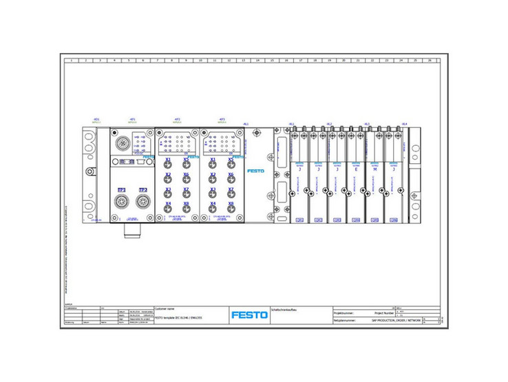
Festo Valve Terminal Configuration Based on EEC

EPLAN and Festo worked together to develop the “Smart Engineering” web service, which enables Festo customers to create a complete EPLAN Project using an app.

Web-Service „Smart Engineering“

The “Smart Engineering” web service enables Festo customers to create a complete EPLAN Project using an app. This means individual configuration of complex products in just a few minutes – including valve terminals and handling systems. EPLAN Engineering Configuration (EEC) in conjunction with EPLAN Fluid and EPLAN Electric P8 serve as the engineering foundation for everything.

We’re Happy to Help!

Would you like to find out more about our solutions or are you interested in our services? Then contact us – we’re here for you!